
 EN
EN
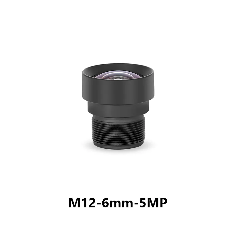
Κατανόηση των Βασικών Αρχών των Φακών M12 για Βιομηχανικές Εφαρμογές
Τι είναι ένας φακός M12 και γιατί κυριαρχεί στη βιομηχανική όραση
Ένα φακός M12—που ονομάστηκε έτσι λόγω της μετρικής σπειροειδούς σύνδεσής του διαμέτρου 12 mm—είναι ένα συμπαγές, τυποποιημένο οπτικό εξάρτημα που έχει σχεδιαστεί για ανθεκτική βιομηχανική απεικόνιση. Η σπειροειδής διεπαφή του επιτρέπει γρήγορη και επαναλαμβανόμενη ενσωμάτωση με μικροσκοπικές κάμερες σε χώρους με περιορισμένο διαθέσιμο χώρο, όπως οι τελικοί εκτελεστές ρομπότ, οι ενσωματωμένοι σταθμοί επιθεώρησης και τα περιφερειακά συστήματα έξυπνων εργοστασίων. Σε αντίθεση με τους όγκινους εναλλακτικούς φακούς τύπου C ή CS, η πλατφόρμα M12 προσφέρει εξαιρετική μηχανική σταθερότητα, αντοχή σε δονήσεις και θερμική αντοχή (–30°C έως 80°C), καθιστώντάς την ιδανική για απαιτητικά βιομηχανικά περιβάλλοντα. Η εντροπική της διαμόρφωση υποστηρίζει την κλιμάκωση σε εφαρμογές όρασης—από την υψηλής ακρίβειας μετρολογία ημιαγωγών μέχρι την παρακολούθηση λογιστικών ροών σε πραγματικό χρόνο. Η χρήση της αυξήθηκε κατά 40% από το 2020 (Imaging Tech Journal, 2023), κυρίως λόγω της αυξανόμενης ζήτησης για αξιόπιστα και επαναφορτώσιμα στο πεδίο οπτικά συστήματα στα πλαίσια της Βιομηχανίας 4.0.
Βασικές Προδιαγραφές: Εστιακή Απόσταση, Διάμετρος Διαφράγματος, Ανάλυση και Συμβατότητα Σύνδεσης
Τέσσερις αλληλεξαρτώμενες προδιαγραφές καθορίζουν την απόδοση φακών M12 σε βιομηχανικές εφαρμογές:
| Προδιαγραφή | Βιομηχανική Επίδραση | Συμβουλή Βελτιστοποίησης |
|---|---|---|
| Εστιακή Απόσταση | Καθορίζει το πεδίο οράσεως (FOV) και την απόσταση λειτουργίας | Χρησιμοποιήστε φακούς 1,5–4 mm για ευρύτερη γωνία επιθεώρησης PCB· φακούς 8–50 mm για εργασίες με στενό πεδίο οράσεως, όπως η ανάγνωση μπαρκοντέρ σε απόσταση |
| Διάμετρος διαφράγματος (f/#) | Ισορροπεί τη διέλευση φωτός και το βάθος πεδίου | Επιλέξτε f/1,4–f/2,0 για σάρωση σε αποθήκες με χαμηλό φωτισμό· f/8+ για εφαρμογές υψηλής αντίθεσης και μεγάλου βάθους πεδίου, όπως η επαλήθευση προσαρμογέων |
| Ψήφισμα | Πρέπει να αναλύει λεπτομέρειες σε συχνότητα ίση ή μεγαλύτερη από το όριο Nyquist του αισθητήρα (≥2× το βήμα pixel) | Συνδυάστε αισθητήρες 5 MP (π.χ. με pixel 2,4 µm) με φακούς που έχουν βαθμολογηθεί ≥150 lp/mm για να αποφύγετε το φαινόμενο aliasing και την θόλωση |
| Συμβατότητα με την εγκατάσταση | Διασφαλίζει τη μηχανική ακεραιότητα και την οπτική στοίχιση | Επιβεβαιώστε το τυποποιημένο βήμα σπείρωμα 0,5 mm και την ακριβή απόσταση εστιακού επιπέδου από τη φλάντζα—οι αποκλίσεις προκαλούν σκίαση (vignetting) ή μετατόπιση εστίασης |
Η βαθμονόμηση της πίσω εστιακής απόστασης είναι αναπόφευκτη: η μη στοίχιση ευθύνεται για το 68 % της αποφεύξιμης εξασθένισης της εικόνας σε εγκαταστάσεις μηχανικής όρασης (Σύνδεσμος A3, 2024). Ελέγξτε πάντα τα πιστοποιητικά περιβαλλοντικής συμβατότητας—ελάχιστο IP67—για αντοχή σε σκόνη και υγρασία σε εγκαταστάσεις παραγωγής.
Πώς να Επιλέξετε το Κατάλληλο Φακός M12 για τη βιομηχανική σας κάμερα Σύστημα
Ταίριασμα του φακού με το μέγεθος του αισθητήρα, την ανάλυση και την απόσταση λειτουργίας
Η επιτυχημένη επιλογή βασίζεται σε τρεις αναπόφευκτες στοιχιοθετήσεις:
- Κάλυψη κύκλου εικόνας : Ο φακός πρέπει να φωτίζει πλήρως τη διαγώνιο του αισθητήρα σας. Ένας αισθητήρας 1/2,5" (διαγώνιος ≈ 7,9 mm) απαιτεί φακό με καθορισμένο κύκλο εικόνας ≥7,9 mm· η χρήση μικρότερου κύκλου προκαλεί έντονη σκίαση (hard vignetting) και σφάλματα μέτρησης.
- Ταίριασμα ανάλυσης : Ένας αισθητήρας 5 MP απαιτεί οπτική ανάλυση ≥150 ζεύγη γραμμών/mm για να αναλύει λεπτές λεπτομέρειες χωρίς θόλωμα. Φακοί χαμηλότερης ανάλυσης περιορίζουν την απόδοση του συστήματος, ανεξάρτητα από τις δυνατότητες του αισθητήρα.
-
Επιβεβαίωση απόστασης λειτουργίας υπολογίστε χρησιμοποιώντας:
Απόσταση Λειτουργίας = Εστιακή Απόσταση × (Πλάτος Αντικειμένου / Πλάτος Αισθητήρα + 1)
Αυτό διασφαλίζει ελάχιστη παραμόρφωση προοπτικής—προϋπόθεση για ακριβή διαστάσεις σε συστήματα καθοδήγησης ρομπότ ή μετρήσεων. Πεδιακά δεδομένα δείχνουν ότι η αντιστοίχιση λανθασμένων αποστάσεων λειτουργίας μειώνει την επαναληψιμότητα των μετρήσεων έως και κατά 40%.
Περιβαλλοντικές Προϋποθέσεις: Θερμοκρασία, Δονήσεις και Απαιτήσεις Βαθμού Προστασίας (IP)
Η βιομηχανική εγκατάσταση απαιτεί περισσότερα από απλά οπτικά χαρακτηριστικά—απαιτεί ενισχυμένη αντοχή σε περιβαλλοντικές συνθήκες:
- Θερμική Σταθερότητα αλουμινένια περιβλήματα και γυάλινα στοιχεία με θερμική αντιστάθμιση διατηρούν την εστίαση σε κύκλους θερμοκρασίας από –30°C έως 80°C—αποτρέποντας την παρέκκλιση εστίασης σε εξωτερικούς κιόσκους ή σε επιθεωρήσεις δίπλα σε φούρνους.
- Αντίσταση σε δονήσεις κόλλες αντι-ξεβίδωματος, κολάρα με διπλούς βίδωτους σφιγκτήρες και αποσβεστήρες κραδασμών από ελαστομερή υλικά μειώνουν την παρέκκλιση της εικόνας κατά 70% σε συστήματα που εγκαθίστανται σε ταινίες μεταφοράς (Έκθεση Βιομηχανικής Οπτικής, 2023).
-
Προστασία Εισόδου επιλέξτε με βάση την έκθεση:
Περιβάλλο Ελάχιστη βαθμίδα IP Εστίαση στην Προστασία Σκονισμένα αποθηκευτικά χώροι IP6X Πλήρης στεγανότητα σε σωματίδια Περιοχές πλύσης IP67 βύθιση 30 λεπτών σε βάθος 1 μέτρου Χημική Εκτέθεια IP69K Αντοχή σε ψεκασμό υψηλής πίεσης και υψηλής θερμοκρασίας
Η παράλειψη αυτών των ελέγχων ενέχει κίνδυνο πρόωρης αποκόλλησης, μετατόπισης εστίασης ή αποτυχίας σφράγισης—ειδικά κατά την επαναλαμβανόμενη θερμική κύκλωση ή τον χημικό καθαρισμό.
Ενσωμάτωση φακών M12 με βιομηχανικές κάμερες: Καλύτερες πρακτικές και παγίδες
Μηχανική στοίχιση, ρύθμιση πίσω εστίασης και μηχανισμοί ασφάλισης
Η ακρίβεια ξεκινά από την εγκατάσταση. ο φακός πρέπει να τοποθετηθεί απόλυτα κάθετα στο επίπεδο του αισθητήρα· απόκλιση γωνίας >0,2° προκαλεί μετρήσιμη παραμόρφωση «keystone» σε εφαρμογές PCB ή μετρολογίας. Η ρύθμιση της πίσω εστίασης—συνήθως μέσω ακριβών ροδελών ή κολλαρδών με ρύθμιση μικρομέτρου—είναι απαραίτητη για αιχμηρή εστίαση σε μικρές αποστάσεις λειτουργίας (<50 cm)· η εσφαλμένη ρύθμιση επιδεινώνει την απόδοση MTF και συνεισφέρει σε πάνω από 60% των αποφεύξιμων αστοχιών που σχετίζονται με την εστίαση (Εκθεση Βιομηχανικής Οπτικής, 2023). Σε περιοχές υψηλής δόνησης, χρησιμοποιήστε διπλή ασφάλιση: ένα βίδι για την προσεγγιστική τοποθέτηση και ένα δευτερεύον κολλαρδό με κόλλα για μόνιμη στερέωση. Αυτό διατηρεί την ευθυγράμμιση κατά τη συνεχή λειτουργία—δεν απαιτείται επανασφίξιμο.
Συνηθισμένα λάθη ενσωμάτωσης και τρόποι αποφυγής επιδείνωσης της ποιότητας εικόνας
Οι πιο συχνές παγίδες είναι αποφεύξιμες:
- Είσοδος σκόνης κατά τη συναρμολόγηση , προκαλώντας μόνιμες «ζεστές κηλίδες» ή απώλεια αντίθεσης—αντιμετωπίστε το με πρωτόκολλα καθαρότητας ISO Class 5 και εργαλεία χειρισμού χωρίς υφές.
- Μετατόπιση του πίσω εστιακού σημείου μετά την εγκατάσταση , συχνά λόγω θερμικής διαστολής ή μηχανικής πλαστικότητας—διαρρύθμιση της εστίασης μετά πλήρης θερμική εξισορρόπηση του συστήματος και επαλήθευση με υψηλής αντίθεσης στόχους USAF 1951.
- Μη συγκέντρωση αισθητήρα-φακού , οδηγώντας σε ασύμμετρη θόλωση ή καμπυλότητα πεδίου—χρησιμοποιήστε ψηφιακούς αισθητήρες κλίσης ή οπτικά εργαλεία συγκέντρωσης για να επιβεβαιώσετε την παραλληλότητα εντός ±0,1°.
Μαζί, αυτές οι πρακτικές μειώνουν τον κίνδυνο επιδείνωσης της ποιότητας της εικόνας έως και κατά 80%, διασφαλίζοντας μακροπρόθεσμη αξιοπιστία σε αυτοματοποιημένες εφαρμογές κρίσιμης σημασίας.
Βελτιστοποίηση της απόδοσης φακών M12 σε πραγματικά βιομηχανικά περιβάλλοντα
Διαρρύθμιση, συνεργασία με το φωτισμό και ανταλλαγές μεταξύ αυτόματης εστίασης και σταθερής εστίασης
Η οπτική απόδοση είναι αδιαχώριστη από το συνολικό σύστημα. Η βαθμονόμηση πρέπει να λαμβάνει υπόψη το φωτισμό: η υποφωτισμένη συνθήκη συρρικνώνει το δυναμικό εύρος και κρύβει ελαττώματα· η υπερέκθεση πληροί τα φωτεινά σημεία και εξασθενεί την αντίθεση στα περιθώρια. Το δομημένο φωτισμό—όπως οι κοαξονικές ή οι δακτυλιοειδώς διασπερμένες πηγές—σε συνδυασμό με επακριβώς ρυθμισμένη διάμετρο διαφράγματος και ενίσχυση μειώνει τις ψευδώς αρνητικές αποφάσεις κατά 32% στην επιθεώρηση ημιαγωγών (μελέτη περίπτωσης κορυφαίου OEM, 2023).
Οι φακοί M12 σταθερής εστίασης κυριαρχούν σε εφαρμογές με σταθερό περιβάλλον (π.χ. αναγνώστες barcode με σταθερή τοποθέτηση ή μετρήσεις σε γραμμές μεταφοράς), μειώνοντας τη συχνότητα συντήρησης κατά 40% σε περιοχές με υψηλή δόνηση. Οι εκδόσεις με αυτόματη εστίαση προσφέρουν ευελιξία για εργασίες με μεταβλητή απόσταση (π.χ. επιλογή αντικειμένων από δοχεία με ρομπότ), αλλά απαιτούν επιπλέον υπολογιστικό φόρτο (+15% φόρτος της CPU) και εισάγουν καθυστέρηση—καθιστώντας τους ακατάλληλους για βρόχους λήψης αποφάσεων υπό 10 ms. Επιλέξτε με βάση τη λειτουργική ακαμψία—όχι την ευκολία.
Παραδείγματα εφαρμογών: Ανάγνωση barcode, Επιθεώρηση PCB και Καθοδήγηση ρομπότ
- Ανάγνωση barcode ένα φακός M12 των 5 MP και 25 mm επιτυγχάνει ακρίβεια αποκωδικοποίησης 99,7 % σε γραμμωτούς ή δισδιάστατους ετικέτες με γρατζουνιές, ανακλαστικές επιφάνειες ή μερική κάλυψη, σε απόσταση 0,5 m — εξασφαλίζοντας αξιόπιστη ταξινόμηση σε κέντρα υψηλής ταχύτητας λογιστικής.
- Πρωτοκόλλων ελέγχου PCB οι τηλεκεντρικοί φακοί M12 παρέχουν επαναληψιμότητα μέτρησης <10 µm για την επαλήθευση των κολλητών συνδέσεων και του πλάτους των ηλεκτρικών διαδρόμων, επιταχύνοντας την απόδοση των συστημάτων οπτικής επιθεώρησης (AOI) κατά 25 % χωρίς να θυσιαστεί η ανίχνευση ελαττωμάτων.
- Καθοδήγηση Ρομπότ οι υπερευρείς φακοί M12 των 1,5 mm (πεδίο οράσεως 90°) παρέχουν πραγματικού χρόνου τοποθεσία αντικειμένων με διόρθωση παραμόρφωσης για ρομπότ pick-and-place — μειώνοντας τα σφάλματα στοίχισης κατά 18 % σε εφαρμογές σώματος αυτοκινήτου.
Συχνές Ερωτήσεις
Ποιό είναι το κύριο πλεονέκτημα της χρήσης φακού M12 σε βιομηχανικές εφαρμογές;
Το κύριο πλεονέκτημα της χρήσης φακού M12 είναι ο μικρός του όγκος και η τυποποιημένη διεπαφή του, που τον καθιστούν κατάλληλο για ενσωμάτωση σε βιομηχανικά περιβάλλοντα με περιορισμένο χώρο, παρέχοντας ταυτόχρονα μηχανική σταθερότητα, αντοχή σε δονήσεις και θερμική αντοχή.
Πώς επιλέγω τον κατάλληλο φακό M12 για το σύστημά μου κάμερας;
Για να επιλέξετε το κατάλληλο φακό M12, διασφαλίστε την ευθυγράμμιση όσον αφορά την κάλυψη του κύκλου εικόνας, την αντιστοιχία ανάλυσης και την απόσταση λειτουργίας. Αυτό διασφαλίζει ότι ο φακός υποστηρίζει πλήρως τις δυνατότητες του αισθητήρα.
Ποια είναι τα συνηθισμένα λάθη κατά την ενσωμάτωση φακών M12 με κάμερες;
Τα συνηθισμένα λάθη περιλαμβάνουν την εισχώρηση σκόνης κατά τη συναρμολόγηση, τη μετατόπιση της πίσω εστίασης μετά την εγκατάσταση και την ανεπαρκή ευθυγράμμιση μεταξύ αισθητήρα και φακού. Αυτά μπορούν να προκαλέσουν επιδείνωση της ποιότητας της εικόνας, αλλά είναι αποφεύξιμα με την τήρηση κατάλληλων διαδικασιών.
Περιεχόμενα
- Κατανόηση των Βασικών Αρχών των Φακών M12 για Βιομηχανικές Εφαρμογές
- Πώς να Επιλέξετε το Κατάλληλο Φακός M12 για τη βιομηχανική σας κάμερα Σύστημα
- Ενσωμάτωση φακών M12 με βιομηχανικές κάμερες: Καλύτερες πρακτικές και παγίδες
- Βελτιστοποίηση της απόδοσης φακών M12 σε πραγματικά βιομηχανικά περιβάλλοντα
- Συχνές Ερωτήσεις